During floods, it is frequently impossible or impractical to measure the peak discharges when they occur because of conditions beyond control. Roads may be impassable; structures from which current-meter measurements might have been made may be nonexistent, not suitably located, or destroyed; knowledge of the flood rise may not be available sufficiently in advance to permit reaching the site near the time of the peak; the peak may be so sharp that a satisfactory current-meter measurement could not be made even with an engineer present at the time; the flow of debris or ice may be such as to prevent use of a current meter; or limitations of personnel might make it impossible to obtain direct measurements of high-stage discharge at numerous locations during a short flood period. Consequently, many peak discharges must be determined after the passage of the flood by indirect methods such as slope-area, contracted opening, flow-overdam, or flow-through-culvert.
Indirect determinations of discharge make use of the energy equation for computing streamflow. The specific equations differ for different types of flow, such as unobstructed open-channel flow, flow over dams, and flow through culverts. However, all the methods involve these general factors:
1. Physical characteristics of the channel; that is dimensions and conformation of the channel within the reach used and boundary conditions.
2. Water-surface elevations at time of peak stage to define the upper limit of the cross-sectional areas and the difference in elevation between two or more significant cross sections.
3. Hydraulic factors based on physical characteristics, water-surface elevations, and discharge, such as roughness coefficients and discharge coefficients.
This chapter provides only a brief general discussion of the procedures used in collecting field data and in computing discharge by the various indirect methods. That highly specialized subject is treated in detail in the several manuals of the series "Techniques of Water Resources Investigations of the United States Geological Survey" that are listed as references at the end of this chapter.
It should be remembered that the discharge that is determined by either direct measurement or by indirect methods includes not only the water but also any substances suspended or dissolved in the water (see chapter 5).
The data required for the computation of discharge by indirect methods are obtained in a field survey of a reach of channel. The survey includes the elevation and location of high-water marks corresponding to the peak stage; cross sections of the channel along the reach; selection of a roughness coefficient; and description of the geometry of dams, culverts, or bridges, depending on the type of peak-discharge determination to be made. The selection of a suitable site is a most important element in the application of the indirect method of discharge determination.
It is recommended that a transit be used to make a "transit-stadia" survey of the selected site. That method combines vertical and horizontal control surveys in one operation and is accurate, simple, and speedy.
Selection of a roughness coefficient remains essentially an "art" that is developed through experience. The factors that exert the greatest influence on the coefficient of roughness are the character of the streambed material, cross section irregularity, the presence of vegetation, and the alinement of the channel. In the Manning equation the roughness coefficient, n, ranges from as low as 0.012 for a concrete-lined channel in excellent condition or for a smooth sand channel of regular geometry to more than 0.1 for overbank areas having a heavy cover of brush.
The slope-area method is the most commonly used technique of indirect discharge determination. In the slope-area method, discharge is computed on the basis of a uniform-flow equation involving channel characteristics, water-surface profiles, and a roughness or retardation coefficient. The drop in water-surface profile for a uniform reach of channel represents energy losses caused by bed and bank roughness.
In applying the slope-area method, any one of the well-known variations of the Chezy equation may be used. However the Manning equation is preferred in most countries, including the U.S.A., because it is simple to apply, and the many years of experience in its use have shown that it produces reliable results.
The manning equation, written in terms of discharge is
Q = (1.486/n) AR2/3S1/2, ( in English units), or (formula 45)
Q = 1/n (AR2/3S1/2) ( in metric units), (formula 45a)
where:
Q = discharge,
A = cross-sectional area,
R = hydraulic radius,
S = friction slope, and
n = roughness coefficient.
The Manning equation was developed for conditions of uniform flow in which the water-surface profile and energy gradient are parallel to the streambed and the area, hydraulic radius, and depth remain constant throughout the reach. For lack of a better solution, it is assumed that the equation is also valid for the nonuniform reaches that are invariably encountered in natural channels, if the water-surface gradient is modified by the difference in velocity-head between cross sections. The energy equation for a reach of nonuniform channel between cross section 1 and cross section 2 shown in figure 9.1. is
(h1+ hv1) = (h2 + hv2) + (hf)1-2+ k (delta hv)1-2, (formula 46)
where:
h = elevation of the water surface at the respective cross sections above a common datum
hv = velocity head at the respective cross sections = (alpha)V2/2g, where (alpha) = velocity-head coefficient,
hf = energy loss due to boundary friction in the reach,
delta hv = upstream velocity head minus the downstream velocity head, used as a criterion for expansion or contraction of reach,
and
k (delta hv) = energy loss due to acceleration or deceleration in a contracting or expanding reach,
where k = energy loss coefficient.
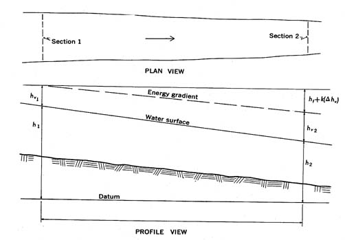
Figure 9.1.- Definition sketch of a slope area reach.
The friction slope (S) to be used in the Manning equation is thus defined as where delta h is the difference in water-surface elevation at the two sections and L is the length of the reach.
S = hf /L = 1/L [delta h + delta hv - k (delta hf)], (formula 47)
In using the Manning equation the conveyance, K, is computed for each cross section as (1.486/n)AR2/3 in English units, or (1/n)AR2/3 in metric units. The mean conveyance in the reach is then computed as the geometric mean of the conveyance at the two sections. This procedure is based on the assumption that the conveyance varies uniformly between sections. The discharge is computed by use of the equation
Q = (K1K2S)1/2, (formula 48)
where S is the friction slope as previously defined.
The contraction of a stream channel by a roadway crossing creates an abrupt drop in water-surface elevation between an approach section and the contracted section under the bridge. The contracted section framed by the bridge abutments and the channel bed is in a sense a discharge meter that can be utilized to compute floodflows. The head on the contracted section is defined by high-water marks, and the geometry of the channel and bridge is defined by field surveys.
In computations of peak discharge at a contraction, the drop in water-surface level between an upstream section and a contracted section is related to the corresponding change in velocity. The discharge equation results from writing the energy and continuity equations for the reach between these two sections, designated as sections 1 and 3 in figure 9.2.
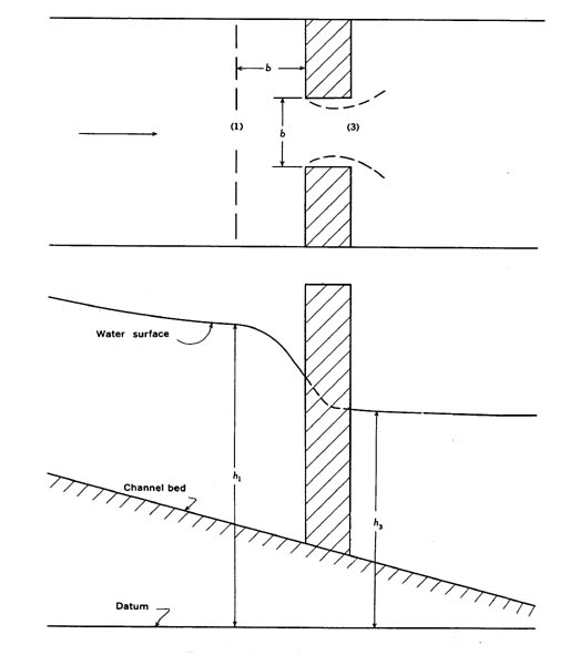
Figure 9.2.- Definition sketch of an open-channel contraction.
The discharge equation is
Q = CA3[2g( delta h + alpha1(V12/2g) - hf]1/2, (formula 49)
in which:
Q = discharge,
g = acceleration of gravity,
C = coefficient of discharge based on the geometry of the bridge and embankment,
A3 = gross area of section 3; this is the minimum section parallel to the constriction between the abutments, and it is not necessarily located at the downstream side of the bridge,
delta h = difference in elevation of the water surface between sections 1 and 3,
alpha1(V12/2g)= weighted average velocity head at section 1, where V, is the average velocity, Q/A1 and alpha1 is coefficient that takes into account the variation in velocity in that section, andhf = the head loss caused by friction between sections 1 and 3.
The friction loss, hf, as computed by the Manning equation, is only an approximation of the actual loss because of the rapid change in velocity from section 1 to section 3. Therefore, satisfactory results are attainable only if the term "hf" is small relative to the difference in head, delta h.
The term "dams," as used here, also includes highway and railway embankments that act as broad-crested dams during floods. The peak discharge over a dam or weir can be determined on the basis of a field survey of high-water marks and the geometry of the particular structure. (The terms "dam" and "weir" are used interchangeably.)
The basic equation for flow over a dam is
Q = CbH3/2, (formula 50)
where:
Q = discharge,
C = a coefficient of discharge having the dimensions of the square root of the acceleration of gravity,
b = width of the dam normal to the flow, excluding the width of piers, if any, and
H = total energy head (h + Va2/2g) referred to the crest of the dam, where h = static head, and Va = mean velocity at the approach section to the dam.
It is apparent from equation 50 that the reliability of a computation of flow over a dam is dependent primarily on using the correct dam coefficient, C. Values of C vary with the geometry of the dam and with the degree of submergence of the dam crest by tailwater. One of the manuals referred to (Hulsing, 1967) treats in detail the coefficients associated with sharp-crested (thin-plate) weirs, broadcrested weirs, round-crested weirs, and weirs of unusual shape. Because the technical details in that manual cannot be readily summarized here, the reader is referred to the Hulsing report.
The peak discharge through culverts can be determined from high-water marks that define the headwater and tailwater elevations. This indirect method is used extensively to measure flood discharges from small drainage areas.
The placement of a roadway fill and culvert in a stream channel causes an abrupt change in the character of flow. This channel transition results in rapidly varied flow in which acceleration, rather than boundary friction, plays the primary role. The flow in the approach channel to the culvert is usually tranquil and fairly uniform. However, within the culvert the flow may be tranquil, critical, or rapid if the culvert is partially filled, or the culvert may flow full under pressure.
The physical features associated with culvert flow are illustrated in figure 9.3. They are the cross section in the approach channel located upstream from the culvert entrance at a distance that is equivalent to the width of the culvert opening; the culvert entrance; the culvert barrel; the culvert outlet; the farthest downstream section of the barrel; and the tailwater downstream from the culvert barrel.
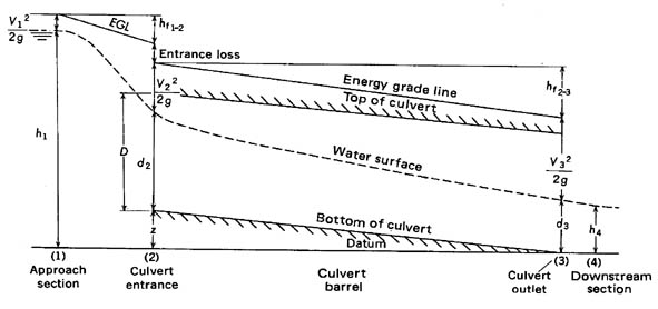
Figure 9.3.- graphical presentation of the Bernoulli equation in culvert flow.
The change in the water-surface profile in the approach channel reflects the effect of acceleration that results from the contraction of cross sectional area. Loss of energy near the entrance is related to the sudden contraction and subsequent expansion of the live stream within the barrel, and entrance geometry has an important influence on this loss. The important features that control the stage-discharge relation at the approach section can be the occurrence of critical depth in the culvert, the elevation of the tailwater, the entrance or barrel geometry, or a combination of these elements.
The peak discharge through a culvert is determined by application of the continuity equation and the energy equation between the approach section and a section within the culvert barrel. The location of the downstream section depends on the state of flow in the culvert barrel. For example, if critical flow occurs at the culvert entrance, the headwater elevation is not a function of either the barrel friction loss or the tailwater elevation, and the terminal section is located at the upstream end of the culvert.
Information obtained in the field survey includes the peak elevation of the water surface upstream and downstream from the culvert and the geometry of the culvert and approach channel. Reliable high-water marks can rarely be found in the culvert barrel; therefore, the type of flow that occurred during the peak flow cannot always be determined directly from field data, and classification becomes a trial-and-error procedure.
GENERAL CLASSIFICATION OF FLOW
For convenience in computation, culvert flow has been classified into six types on the basis of the location of the control section and the relative heights of the headwater and tailwater elevations. The six types of flow are illustrated in figure 9.4., and pertinent characteristics of each type are given in table 15. From that information the general classification of types of flow can be made.
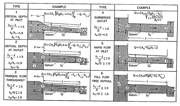
Figure 9.4.- Classification of culvert flow.
A manual by Bodhaine (1968) discusses trial-and-error procedures for further identification of the type of culvert flow and for the computation of discharge.
Situations exist where none of the four methods previously described for determining peak discharge can be reliably applied. For example, in a highly sinuous, steep canyon stream, there may be no straight reaches of sufficient length for reliable application of the slope-area method; no abrupt area contractions may exist; and no man-made structures, such as dams or culverts, may have been built. In the above situation the peak discharge may sometimes be estimated from the superelevation in a bend of the stream (Apmann, 1973). The discharge should be estimated at each of several bends, after which the several estimated discharges are averaged.
A fundamental characteristic of open channel flow is the deformation of the free surface in a bend because of the action of centrifugal force. The water surface rises on the concave or outside bank of the bend and lowers along the convex or inside bank of the bend. The difference in water-surface elevation between the banks is the superelevation. Superelevation varies with angular distance in the bend because of acceleration of the fluid entering and leaving the curve and because of the varying curvature of streamlines within the bend.
The discharge equation given by Apmann (1973) is
Q = A (gh/K)1/2 (formula 51)
where:
Q = discharge,
A = average radial cross section in the bend,
g = acceleration of gravity,
h = superelevation, that is, the maximum difference in watersurface elevation, measured along a radius of the bend, between inner and. outer banks of the bend, and
K = superelevation coefficient.
The value of K is determined from the equation
K =
5/4tan h
(rcO/b)ln
(ro/ri).
(formula 52)
(NOTE.-tan h is the hyperbolic tangent)
The symbols in equation 52 are shown in the sketch in figure 138.
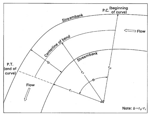
Figure 9.5.- Idealized sketch of a bend (plan view).
The method described applies only to bends having no overbank flow. The limited amount of work that has been done with the method indicates that it should not be applied where superelevations are less than 0.25 ft. (0.076 m.) because of uncertainties regarding the elevations of high-water marks at the banks. These uncertainties result from wave action and from the thickness of the bank-deposited debris that is often used as a high-water mark.
American Society of Civil Engineers, 1975, Sedimentation engineering: A.S.C.E. Manuals and Reports on Engineering Practice no. 54, 745 p.
Apmann, R. P., 1973, Estimating discharge from superelevation in bends: Am. Soc.Civil Engineers, Hydraulics Div. Jour., v. 99, no. HY1, p. 65-79.
Benson, M. A., and Dalrymple, Tate, 1967, General field and office procedures for indirect discharge measurements: U.S. Geol. Survey Techniques Water-Resources Inv., book 3, chap. Al, 30 p.
Bodhaine, G. L., 1968, Measurement of peak discharge at culverts by indirect methods:U.S. Geol. Survey Techniques Water-Resources Inv., book 3, chap. A3, 60 p.
Dalrymple, Tate, and Benson, M. A., 1967, Measurement of peak discharge by the slope-area method: U.S. Geol. Survey Techniques Water-Resources Inv., book 3, chap. A2, 12 p.
Hulsing, Harry, 1967, Measurement of peak discharge at dams by indirect methods: U.S. Geol. Survey Techniques Water-Resources Inv., book 3, chap. A5, 29 p.
Matthai, H. F., 1967, Measurement of peak discharge at width contractions: U.S. Geol. Survey Techniques Water-Resources Inv., book 3. chap. A4, 44 p.